Vertex Input Data Processing
This chapter is an overview of the Fixed-Function Vertex Processing chapter in the spec to help give a high level understanding of how an application can map data to the vertex shader when using a graphics pipeline.
It is also important to remember that Vulkan is a tool that can be used in different ways. The following are examples for educational purposes of how vertex data can be laid out.
For more information about Location and Component, see the Location and Component Interface chapter.
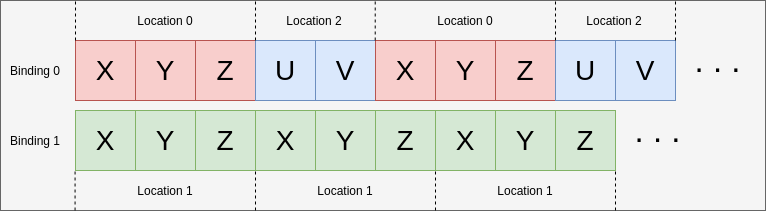
Binding and Locations
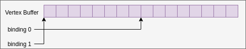
A binding is tied to a position in the vertex buffer from which the vertex shader will start reading data out of during a vkCmdDraw* call. Changing the bindings does not require making any alterations to an app’s vertex shader source code.
As an example, the following code matches the diagram of how bindings work.
// Using the same buffer for both bindings in this example
VkBuffer buffers[] = { vertex_buffer, vertex_buffer };
VkDeviceSize offsets[] = { 8, 0 };

vkCmdBindVertexBuffers(
                        my_command_buffer, // commandBuffer
                        0,                 // firstBinding
                        2,                 // bindingCount
                        buffers,           // pBuffers
                        offsets,           // pOffsets
                      );
The following examples show various ways to set your binding and location values depending on your data input.
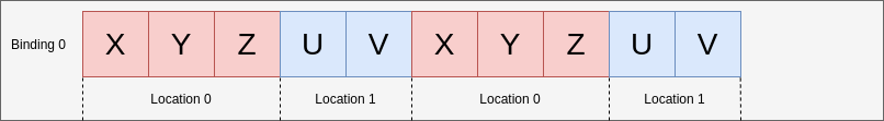
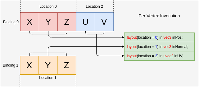
Example A - packed data
For the first example, the per-vertex attribute data will look like:
struct Vertex {
    float   x, y, z;
    uint8_t u, v;
};
The pipeline create info code will look roughly like:
const VkVertexInputBindingDescription binding = {
    0,                          // binding
    sizeof(Vertex),             // stride
    VK_VERTEX_INPUT_RATE_VERTEX // inputRate
};

const VkVertexInputAttributeDescription attributes[] = {
    {
        0,                          // location
        binding.binding,            // binding
        VK_FORMAT_R32G32B32_SFLOAT, // format
        0                           // offset
    },
    {
        1,                          // location
        binding.binding,            // binding
        VK_FORMAT_R8G8_UNORM,       // format
        3 * sizeof(float)           // offset
    }
};

const VkPipelineVertexInputStateCreateInfo info = {
    1,             // vertexBindingDescriptionCount
    &binding,      // pVertexBindingDescriptions
    2,             // vertexAttributeDescriptionCount
    &attributes[0] // pVertexAttributeDescriptions
};
The GLSL code that would consume this could look like
layout(location = 0) in vec3 inPos;
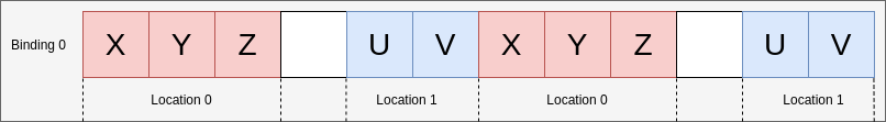
layout(location = 1) in uvec2 inUV;Example B - padding and adjusting offset
This example examines a case where the vertex data is not tightly packed and has extra padding.
struct Vertex {
    float   x, y, z, pad;
    uint8_t u, v;
};
The only change needed is to adjust the offset at pipeline creation
        1,                          // location
        binding.binding,            // binding
        VK_FORMAT_R8G8_UNORM,       // format
-        3 * sizeof(float)           // offset
+        4 * sizeof(float)           // offset
As this will now set the correct offset for where u and v are read in from.
Example C - non-interleaved
Sometimes data is not interleaved, in this case, you might have the following
float position_data[] = { /*....*/ };
uint8_t uv_data[] = { /*....*/ };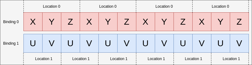
In this case, there will be 2 bindings, but still 2 locations
const VkVertexInputBindingDescription bindings[] = {
    {
        0,                          // binding
        3 * sizeof(float),          // stride
        VK_VERTEX_INPUT_RATE_VERTEX // inputRate
    },
    {
        1,                          // binding
        2 * sizeof(uint8_t),        // stride
        VK_VERTEX_INPUT_RATE_VERTEX // inputRate
    }
};

const VkVertexInputAttributeDescription attributes[] = {
    {
        0,                          // location
        bindings[0].binding,        // binding
        VK_FORMAT_R32G32B32_SFLOAT, // format
        0                           // offset
    },
    {
        1,                          // location
        bindings[1].binding,        // binding
        VK_FORMAT_R8G8_UNORM,       // format
        0                           // offset
    }
};

const VkPipelineVertexInputStateCreateInfo info = {
    2,             // vertexBindingDescriptionCount
    &bindings[0],  // pVertexBindingDescriptions
    2,             // vertexAttributeDescriptionCount
    &attributes[0] // pVertexAttributeDescriptions
};
The GLSL code does not change from Example A
layout(location = 0) in vec3 inPos;
layout(location = 1) in uvec2 inUV;
Example D - 2 bindings and 3 locations
This example is to help illustrate that the binding and location are independent of each other.
In this example, the data of the vertices is laid out in two buffers provided in the following format:
struct typeA {
    float   x, y, z; // position
    uint8_t u, v;    // UV
};

struct typeB {
    float x, y, z; // normal
};

typeA a[] = { /*....*/ };
typeB b[] = { /*....*/ };
and the shader being used has the interface of
layout(location = 0) in vec3 inPos;
layout(location = 1) in vec3 inNormal;
layout(location = 2) in uvec2 inUV;
The following can still be mapped properly by setting the VkVertexInputBindingDescription and VkVertexInputAttributeDescription accordingly:
const VkVertexInputBindingDescription bindings[] = {
    {
        0,                          // binding
        sizeof(typeA),              // stride
        VK_VERTEX_INPUT_RATE_VERTEX // inputRate
    },
    {
        1,                          // binding
        sizeof(typeB),              // stride
        VK_VERTEX_INPUT_RATE_VERTEX // inputRate
    }
};

const VkVertexInputAttributeDescription attributes[] = {
    {
        0,                          // location
        bindings[0].binding,        // binding
        VK_FORMAT_R32G32B32_SFLOAT, // format
        0                           // offset
    },
    {
        1,                          // location
        bindings[1].binding,        // binding
        VK_FORMAT_R32G32B32_SFLOAT, // format
        0                           // offset
    },
    {
        2,                          // location
        bindings[0].binding,        // binding
        VK_FORMAT_R8G8_UNORM,       // format
        3 * sizeof(float)           // offset
    }
};
Example E - understanding input attribute format
The VkVertexInputAttributeDescription::format can be the cause of confusion. The format field just describes the size and type of the data the shader should read in.
The reason for using the VkFormat values is they are well defined and match the input layouts of the vertex shader.
For this example the vertex data is just four floats:
struct Vertex {
    float a, b, c, d;
};
The data being read will be overlapped from how the format and offset is set
const VkVertexInputBindingDescription binding = {
    0,                          // binding
    sizeof(Vertex),             // stride
    VK_VERTEX_INPUT_RATE_VERTEX // inputRate
};

const VkVertexInputAttributeDescription attributes[] = {
    {
        0,                          // location
        binding.binding,            // binding
        VK_FORMAT_R32G32_SFLOAT,    // format - Reads in two 32-bit signed floats ('a' and 'b')
        0                           // offset
    },
    {
        1,                          // location
        binding.binding,            // binding
        VK_FORMAT_R32G32B32_SFLOAT, // format - Reads in three 32-bit signed floats ('b', 'c', and 'd')
        1 * sizeof(float)           // offset
    }
};
When reading in the data in the shader the value will be the same where it overlaps
layout(location = 0) in vec2 in0;
layout(location = 1) in vec2 in1;

// in0.y == in1.x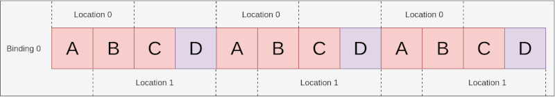
It is important to notice that in1 is a vec2 while the input attribute is VK_FORMAT_R32G32B32_SFLOAT which doesn’t fully match. According to the spec:
If the vertex shader has fewer components, the extra components are discarded.
So in this case, the last component of location 1 (d) is discarded and would not be read in by the shader.
Components Assignment
The spec explains more in detail about the Component assignment. The following is a general overview of the topic.
Filling in components
Each location in the VkVertexInputAttributeDescription has 4 components. The example above already showed that extra components from the format are discarded when the shader input has fewer components.
VK_FORMAT_R32G32B32_SFLOAThas 3 components while avec2has only 2
For the opposite case, the spec has a table showing how it will expand missing components.
This means the example of
layout(location = 0) in vec3 inPos;
layout(location = 1) in uvec2 inUV;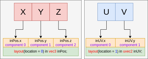
would fill the examples above with the following
layout(location = 0) in vec4 inPos;
layout(location = 1) in uvec4 inUV;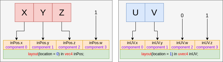
Setting the stride
Over time, the number of ways to set the stride of a vertex input binding has grown.
Originally, when using vkCmdBindVertexBuffers, the stride value was defined within the pipeline via VkVertexInputBindingDescription::stride. At draw time, the combination of vkCmdBindPipeline and vkCmdBindVertexBuffers provided all the necessary state.
Later, VK_EXT_vertex_input_dynamic_state was added. This introduced VK_DYNAMIC_STATE_VERTEX_INPUT_EXT, allowing applications to skip defining vertex input values in the pipeline. Instead, you call vkCmdSetVertexInputEXT inside the command buffer to set VkVertexInputBindingDescription2EXT::stride, along with all other vertex input values.
Subsequently, VK_EXT_extended_dynamic_state introduced VK_DYNAMIC_STATE_VERTEX_INPUT_BINDING_STRIDE. This allows the pipeline to skip the VkVertexInputBindingDescription::stride definition. Instead, the stride is set dynamically via vkCmdBindVertexBuffers2.
An issue arose because the stride could be set by both vkCmdSetVertexInputEXT and vkCmdBindVertexBuffers2 prior to a draw. It was determined that the last value set prior to the draw call is the one that will be used.
When vkCmdBindVertexBuffers3KHR was added, it introduced VkBindVertexBuffer3InfoKHR::setStride. This allows the user to decide whether the function should update the stride value or leave it unchanged before a draw.