Appendix:
Detailed Architectural Patterns
This appendix provides in-depth information about common architectural patterns used in modern rendering and game engines. These patterns are referenced in the main Engine Architecture section, with a focus on Component-Based Architecture in the main tutorial.
Layered Architecture
One of the most fundamental architectural patterns is the layered architecture, where the system is divided into distinct layers, each with a specific responsibility.
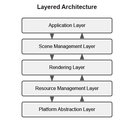
Typical Layers in a Rendering Engine
-
Platform Abstraction Layer - Provides a consistent interface to platform-specific functionality.
-
Resource Management Layer - Manages loading, caching, and unloading of assets.
-
Rendering Layer - Handles the rendering pipeline, shaders, and graphics API interaction.
-
Scene Management Layer - Manages the scene graph, spatial partitioning, and culling.
-
Application Layer - Handles user input, game logic, and high-level application flow.
Benefits of Layered Architecture
-
Clear separation of concerns
-
Easier to understand and maintain
-
Can replace or modify individual layers without affecting others
-
Facilitates testing of individual layers
Implementation Example
// Platform Abstraction Layer
class Platform {
public:
    virtual void Initialize() = 0;
    virtual void* CreateWindow(int width, int height) = 0;
    virtual void ProcessEvents() = 0;
    // ...
};

// Resource Management Layer
class ResourceManager {
public:
    virtual Texture* LoadTexture(const std::string& path) = 0;
    virtual Mesh* LoadMesh(const std::string& path) = 0;
    // ...
};

// Rendering Layer
class Renderer {
public:
    virtual void Initialize(Platform* platform) = 0;
    virtual void RenderScene(Scene* scene) = 0;
    // ...
};

// Scene Management Layer
class SceneManager {
public:
    virtual void AddEntity(Entity* entity) = 0;
    virtual void UpdateScene(float deltaTime) = 0;
    // ...
};

// Application Layer
class Application {
private:
    Platform* platform;
    ResourceManager* resourceManager;
    Renderer* renderer;
    SceneManager* sceneManager;

public:
    void Run() {
        platform->Initialize();
        renderer->Initialize(platform);

        // Main loop
        while (running) {
            platform->ProcessEvents();
            sceneManager->UpdateScene(deltaTime);
            renderer->RenderScene(sceneManager->GetActiveScene());
        }
    }
};
Data-Oriented Design
Data-Oriented Design (DOD) focuses on organizing data for efficient processing, rather than organizing code around objects.

Key Concepts
-
Data Layout - Organizing data for cache-friendly access patterns.
-
Systems - Process data in bulk, often using SIMD instructions.
-
Entity-Component-System (ECS) - A common implementation of DOD principles.
Benefits of Data-Oriented Design
-
Better cache utilization
-
More efficient memory usage
-
Easier to parallelize
-
Can lead to significant performance improvements
Implementation Example
// A simple ECS implementation
struct TransformData {
    std::vector<glm::vec3> positions;
    std::vector<glm::quat> rotations;
    std::vector<glm::vec3> scales;
};

struct RenderData {
    std::vector<Mesh*> meshes;
    std::vector<Material*> materials;
};

class TransformSystem {
private:
    TransformData& transformData;

public:
    TransformSystem(TransformData& data) : transformData(data) {}

    void Update(float deltaTime) {
        // Process all transforms in bulk
        for (size_t i = 0; i < transformData.positions.size(); ++i) {
            // Update transforms
        }
    }
};

class RenderSystem {
private:
    RenderData& renderData;
    TransformData& transformData;

public:
    RenderSystem(RenderData& rData, TransformData& tData)
        : renderData(rData), transformData(tData) {}

    void Render() {
        // Render all entities in bulk
        for (size_t i = 0; i < renderData.meshes.size(); ++i) {
            // Render mesh with transform
        }
    }
};
Service Locator Pattern
The Service Locator pattern provides a global point of access to services without coupling consumers to concrete implementations.

Key Concepts
-
Service Interface - Defines the contract for a service.
-
Service Provider - Implements the service interface.
-
Service Locator - Provides access to services.
Benefits of Service Locator Pattern
-
Decouples service consumers from service providers
-
Allows for easy service replacement
-
Facilitates testing with mock services
Implementation Example
// Audio service interface
class IAudioService {
public:
    virtual ~IAudioService() = default;
    virtual void PlaySound(const std::string& soundName) = 0;
    virtual void StopSound(const std::string& soundName) = 0;
};

// Concrete audio service
class OpenALAudioService : public IAudioService {
public:
    void PlaySound(const std::string& soundName) override {
        // Implementation using OpenAL
    }

    void StopSound(const std::string& soundName) override {
        // Implementation using OpenAL
    }
};

// Service locator
class ServiceLocator {
private:
    static IAudioService* audioService;
    static IAudioService nullAudioService; // Default null service

public:
    static void Initialize() {
        audioService = &nullAudioService;
    }

    static IAudioService& GetAudioService() {
        return *audioService;
    }

    static void ProvideAudioService(IAudioService* service) {
        if (service == nullptr) {
            audioService = &nullAudioService;
        } else {
            audioService = service;
        }
    }
};

// Usage example
void PlayGameSound() {
    ServiceLocator::GetAudioService().PlaySound("explosion");
}
Comparative Analysis of Architectural Patterns
Below is a comparative analysis of the architectural patterns discussed in this appendix:
| Pattern | Strengths | Weaknesses | Best Used For |
|---|---|---|---|
Layered Architecture |
|
|
|
Component-Based Architecture |
|
|
|
Data-Oriented Design |
|
|
|
Service Locator Pattern |
|
|
|
Advanced Rendering Techniques
This section provides an overview of advanced rendering techniques commonly used in modern rendering engines. For more comprehensive information, refer to these excellent resources:
-
Physically Based Rendering: From Theory to Implementation - https://www.pbr-book.org/
-
Real-Time Rendering - https://www.realtimerendering.com/
-
GPU Gems series - https://developer.nvidia.com/gpugems/gpugems/contributors
Deferred Rendering
Deferred rendering separates the geometry and lighting calculations into separate passes, which can be more efficient for scenes with many lights:
-
Geometry Pass - Render scene geometry to G-buffer textures (position, normal, albedo, etc.).
-
Lighting Pass - Apply lighting calculations using G-buffer textures.
Forward+ Rendering
Forward+ (or tiled forward) rendering combines the simplicity of forward rendering with some of the efficiency benefits of deferred rendering:
-
Light Culling Pass - Divide the screen into tiles and determine which lights affect each tile.
-
Forward Rendering Pass - Render scene geometry with only the lights that affect each tile.
Physically Based Rendering (PBR)
PBR aims to create more realistic materials by simulating how light interacts with surfaces in the real world:
-
Material Parameters - Define materials using physically meaningful parameters (albedo, metalness, roughness, etc.).
-
BRDF - Use a physically based bidirectional reflectance distribution function.
-
Image-Based Lighting - Use environment maps for ambient lighting.
Advanced Camera Techniques
This section covers advanced techniques for implementing sophisticated camera systems in 3D applications:
-
Camera Collision: Implement a collision volume for the camera to prevent it from passing through walls
-
Context-Aware Positioning: Adjust camera position based on the environment (e.g., zoom out in large open areas, zoom in in tight spaces)
-
Intelligent Framing: Adjust the camera to keep both the character and important objects in frame
-
Predictive Following: Anticipate character movement to reduce camera lag
-
Camera Obstruction Transparency: Make objects that obstruct the view partially transparent
-
Dynamic Field of View: Adjust the FOV based on movement speed or environmental context
Conclusion
These architectural patterns and rendering techniques provide a foundation for designing your rendering engine. In practice, most engines use a combination of these patterns to address different aspects of the system.
When designing your engine architecture, consider:
-
Performance Requirements - Different patterns have different performance characteristics.
-
Flexibility Needs - How much flexibility do you need for future extensions?
-
Team Size and Experience - More complex architectures may be harder to work with for smaller teams.
-
Project Scope - A small project may not need the complexity of a full ECS.