Ray tracing - reflection
| The source for this sample can be found in the Khronos Vulkan samples github repository. |
Overview
This sample is a extended version of the ray tracing basic with the addition of multiple geometries, instances and materials.
In addition, this sample is showing how to cast shadow rays and reflections.
Geometries, bottom, and top-level acceleration structures
The structures of the geometry are like those described in the OBJ format. For our geometry there is a list of vertices (position and normal) and a triplet of indices for each triangle.
Each triangle also has an index for a material. In this example, each object has its own list of materials, but we could have made it so that the materials are shared by all objects in the scene.
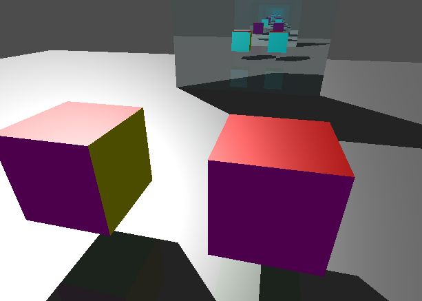
The example scene has two geometries: a plane and a cube.
You can see the creation of the scene under RaytracingReflection::create_scene().
create_model()
This function allocates and upload the geometry to the GPU. There are four buffers per geometry.
-
Vertices: the position and normal
-
Indices: index of vertex to form a triangle
-
Material index: material id per triangle
-
Materials: a list of materials (albedo, specular, reflection)
create_buffer_references()
In this example, buffer references are used. Instead of having a descriptor set with multiple arrays to access the buffers, we create a buffer that contains the addresses of the scene models. With this method, we can easily access the data of the model we hit in the shader.
In the shader, VkDeviceAddress are uint64_t, therefore we will access a buffer of an array of structure ObjBuffers.
struct ObjBuffers
{
 uint64_t vertices;
 uint64_t indices;
 uint64_t materials;
 uint64_t materialIndices;
};
layout(set = 0, binding = 3)    buffer _scene_desc { ObjBuffers i[]; } scene_desc;
The addresses correspond to buffers, so we will declare them like this:
layout(buffer_reference, scalar) buffer Vertices {Vertex v[]; }; // Positions of an object
layout(buffer_reference, scalar) buffer Indices {uvec3 i[]; }; // Triangle indices
layout(buffer_reference, scalar) buffer Materials {WaveFrontMaterial m[]; }; // Array of all materials on an object
layout(buffer_reference, scalar) buffer MatIndices {int i[]; }; // Material ID for each triangle
The in the shader, to access the data of an object, we will do the following:
 ObjBuffers objResource = scene_desc.i[gl_InstanceCustomIndexEXT];
 MatIndices matIndices  = MatIndices(objResource.materialIndices);
 Materials  materials   = Materials(objResource.materials);
 Indices    indices     = Indices(objResource.indices);
 Vertices   vertices    = Vertices(objResource.vertices);
Note that gl_InstanceCustomIndexEXT was set with one of the three scene objects.
See RaytracingReflection::create_blas_instance.
create_bottom_level_acceleration_structure()
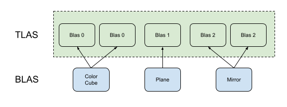
We build a lower-level acceleration structure (BLAS) for each geometry: a cube with one material on each face (0), a plane (1), and a mirror cube (2).
These BLAS are instantiated by the top-level acceleration structure (TLAS) with a transformation matrix.
In this example w are calling separately the construction of all BLAS, allocating scratch buffer each time.
A better way would be to build them, knowing the size the biggest scratch buffer and doing all at once.
Also provide in the helper , is the ability to compact the memory used to store the BLAS when using the VK_BUILD_ACCELERATION_STRUCTURE_ALLOW_COMPACTION_BIT_KHR flag.
create_top_level_acceleration_structure()
The top-level acceleration structure (TLAS) embeds multiple BLAS.
It is possible to reuse the same BLAS and give it a different transformation matrix to place it in a different position in the scene.
We see this in create_scene(), the same BLAS id is reused with different matrices.
Note, the BLAS id will be identified by the gl_InstanceCustomIndexEXT in the shader.
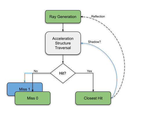
Ray tracing pipeline
The difference with ray tracing basic, is the addition of the second miss-shade module. This is called from the closest-hit shader to detect if there is an object between the hit point and the light.
More on ray tracing pipeline here.
Shadows
In the closest-hit shader, we trace a ray to determine if there is an object between the hit point and the light.
For this trace ray, we use the shadow-miss shader (index 1) and a different payload (index 1) that contains only one boolean value, "isShadowed".
We assume that an object is blocking the light, so we initialize the value to true.
Then, if the ray hits nothing, we set this value to false.
The origin of the ray is the hit position and the direction of the ray is toward the light. Note, we are using an hardcoded infinite light L.
This method for shooting shadow rays is fast because we set the trace flag to skip execution of the closest-hit and terminate on the first hit, then only execute the shadow-miss-shader and set a small payload.
uint flags = gl_RayFlagsTerminateOnFirstHitEXT | gl_RayFlagsOpaqueEXT | gl_RayFlagsSkipClosestHitShaderEXT;Reflection
For reflection, we do not change maxPipelineRayRecursionDepth and leave the value at 2.
Instead of recursively looping from the closest-hit shader, we store the information of the next ray in the payload and send new rays from the ray generation shader.
When we call traceRayEXT from the closest-hit shader, it must store the state of all variables needed after execution.
Recursively calling traceRayEXT requires storing a lot of data per ray call, and that is typically slow.
Instead, we store in the payload the ray origin and the ray direction that the ray generation shader will use. This method also removes the pipeline ray recursion depth constraint.
Here is how the payload is defined:
struct hitPayload
{
 vec3 radiance;
 vec3 attenuation;
 int  done;
 vec3 rayOrigin;
 vec3 rayDir;
};
The radiance is the value at the point of impact multiplied by the attenuation.
The first time the attenuation is vec3(1) (no attenuation), but the shininess of the material reduces the attenuation in the following hits.
After a few passes, the radiance will be close to vec3(0).
The done is an indication that the ray did not hit anything.
The miss shader sets it to true and the loop can be terminated.
The origin of the ray starts at the camera, and is replaced by the position of the target.
The direction starts at the camera direction, and then is reflected purely at the surface of the object.
The recursion limit is set in the ray-generation shader. Currently it is set to 64, changing its value will change the number of times the ray bounces off.
| we could add a test on the attenuation and exist the loop if the value is below a certain threshold. |
Other Tutorial
The following tutorial is showing the limitation of hitting the recursion limits. Note, the spec does not guarantee a recursion check at runtime. If you exceed either the recursion depth you reported in the raytrace pipeline create info, or the physical device recursion limit, undefined behavior results.